Forums » Input, Adapters & Controllers » Control Box Video?

1
Wow, it looks like the forums have been completely revamped since the last time I was here. O.o
Anyways, a while back, I posted a thread looking to buy a control box for by Metal Blue Shark pad. The only response I ended up getting was from a dude on the forums named PrayerWarrior, who said I would be better off building one. Well... Long story short, I'm now looking to actually construct said control box, but being that the forum got revamped, and I see no way to message PrayerWarrior, I was wondering if anyone could lead the way towards the video he said he was recording about building it or possibly a tutorial to create a control box for it or something? Thanks in advance. :)

EDIT: Would a possible workaround for this also be getting a D-SUB 15 pin cable (I keep seeing the 15-pin D-SUB cables referred to as VGA ports though...) to USB adapter? I could understand it maybe working in theory, but my only question would be how the computer would recognize the input... Would it be on the VGA to USB adapter board or something?

Last edited: 20 July 2014 10:49pm
Reply
Where do you get d-sub 15-pin cables at?

I've always just got the d-subs and soldered my wires on directly.

Anyways for the Blue Shark pad you WILL NEED to figure out where the GROUND pin is first. Get a working soft pad and rip the circuit board out of it, sand down the black terminals to reveal metal then with your d-sub cable attach ALL WIRES to Ground at the same time then have someone stand on an arrow. Keep removing one wire at a time until the arrow stops working. The last wire you removed was either THAT ARROW OR Ground. There may be two inputs per arrow with the Blue Shark, and there may be more than one Ground wire. Just keep doing this process and label each wire you determine. Then when you have the wiring all figured out (I'm going to assume that at least some of the wires go to nothing) you can solder these wires to the circuit board you were messing around with.

You may also want to solder some small capacitors in-line as the Blue Sharks are known to carry static.

I do the Precision Dance Pads, and I even sell Cobalt Flux replacement control boxes on my site because so many people asked for them, but I don't have the pin-out for a blue shark. The only circuit board I would use for a blue shark would be our multi-console control box because it has capacitors for all the inputs. I could build you one if you can confirm the pinout below, but other than soldering up the d-sub the rest is pretty easy to do.

According to this there are just 7 inputs used, and the output is a d-sub 15 male, so your control box will be a d-sub 15 female. I wouldn't 100% trust the data but if there are just 7 wires going in the pad then that would be a very positive assurance.

http://imgur.com/gallery/8OKlX

The Pinout - Button - Color of wire

Pin 5 - Ground - Black
Pin 7 - Up - Gray
Pin 8 - Down - Green
Pin 9 - Left - Orange
Pin 10 - Right - Blue
Pin 14 - OA - White
Pin 15 - XB - Purple

Last edited: 23 July 2014 12:08am

Reply
Where do you get d-sub 15-pin cables at?

I've always just got the d-subs and soldered my wires on directly.

Anyways for the Blue Shark pad you WILL NEED to figure out where the GROUND pin is first. Get a working soft pad and rip the circuit board out of it, sand down the black terminals to reveal metal then with your d-sub cable attach ALL WIRES to Ground at the same time then have someone stand on an arrow. Keep removing one wire at a time until the arrow stops working. The last wire you removed was either THAT ARROW OR Ground. There may be two inputs per arrow with the Blue Shark, and there may be more than one Ground wire. Just keep doing this process and label each wire you determine. Then when you have the wiring all figured out (I'm going to assume that at least some of the wires go to nothing) you can solder these wires to the circuit board you were messing around with.

You may also want to solder some small capacitors in-line as the Blue Sharks are known to carry static.

I do the Precision Dance Pads, and I even sell Cobalt Flux replacement control boxes on my site because so many people asked for them, but I don't have the pin-out for a blue shark. The only circuit board I would use for a blue shark would be our multi-console control box because it has capacitors for all the inputs. I could build you one if you can confirm the pinout below, but other than soldering up the d-sub the rest is pretty easy to do.

According to this there are just 7 inputs used, and the output is a d-sub 15 male, so your control box will be a d-sub 15 female. I wouldn't 100% trust the data but if there are just 7 wires going in the pad then that would be a very positive assurance.

http://imgur.com/gallery/8OKlX

The Pinout - Button - Color of wire

Pin 5 - Ground - Black
Pin 7 - Up - Gray
Pin 8 - Down - Green
Pin 9 - Left - Orange
Pin 10 - Right - Blue
Pin 14 - OA - White
Pin 15 - XB - Purple


Alright, I purchased a new pad. I tore apart one of the control boxes I had and did a looksie at the board. Relooking it over a few years later shows some wear and tear to it, possibly electrical damage...
Anways! The soft pad I purchased apparently has the buttons labeled for what each cable leads to. Assuming that the D-SUB wiring that you posted is the same, couldn't I just solder the cables to the board on each point where it says the wire should go? I'm going to pull the old D-SUB female connector from the box and use it to connect the wires to the board.
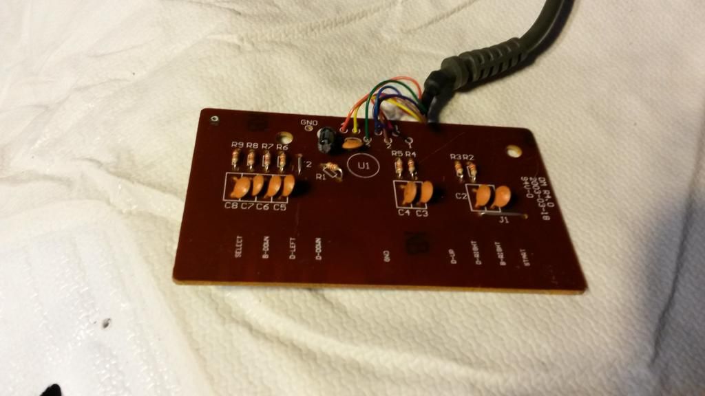
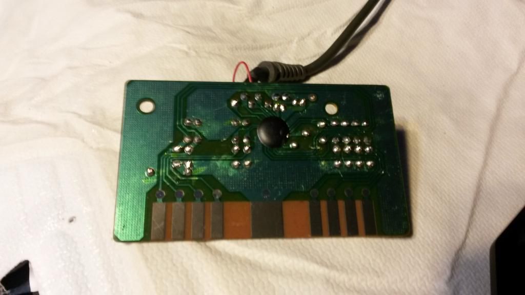
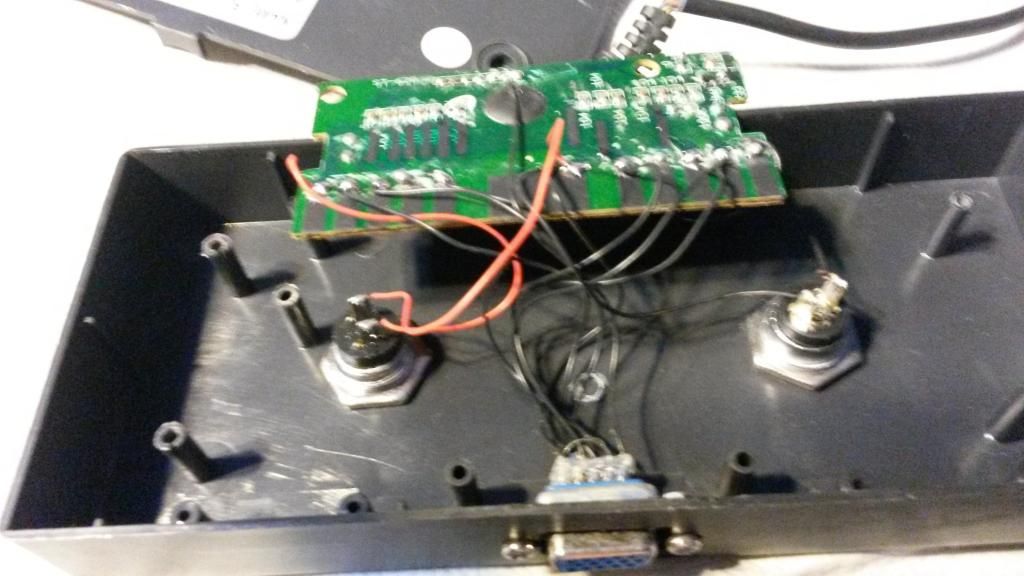
Here are some pics for clarification:

Old MyMyBox control box and board (Closeup mostly of the D-SUB port)


Front of board from new pad


Back of board from new pad


On another side note, apparently the points where the board screws into the box are in the same place, so I can use the same control box. Being that the case, the start/select buttons have two wires running off them, as shown in the first picture. Could I not just take off one of the cables and run one of them to the board and use that to be a start/select button, since the two cables are probably just there as kind of a switch, and pushing down on the buttons just continues the circuit?

Last edited: 25 July 2014 8:03pm

Reply
Alright, I purchased a new pad. I tore apart one of the control boxes I had and did a looksie at the board. Relooking it over a few years later shows some wear and tear to it, possibly electrical damage...
Anways! The soft pad I purchased apparently has the buttons labeled for what each cable leads to. Assuming that the D-SUB wiring that you posted is the same, couldn't I just solder the cables to the board on each point where it says the wire should go? I'm going to pull the old D-SUB female connector from the box and use it to connect the wires to the board.
Here are some pics for clarification:

On another side note, apparently the points where the board screws into the box are in the same place, so I can use the same control box. Being that the case, the start/select buttons have two wires running off them, as shown in the first picture. Could I not just take off one of the cables and run one of them to the board and use that to be a start/select button, since the two cables are probably just there as kind of a switch, and pushing down on the buttons just continues the circuit?

That will be easy to do, go for it. Make sure to use some sand-paper on the new circuit board on the black terminals until you see shiny metal but not too much as the metal will rub off if you do it too much.

I can't see two wires going to Start / Select. On the box leave those two buttons and wire them up accordingly one wire to Start OR Select and another to Ground, so you'll have THREE WIRES going to ground. That black wire that goes all the way up I don't get it try to just solder that wire to ground as well. Watch my video it will make alot of sense. Drilling the holes is optional. The board you have will be great it has capacitors to help with static probably better than the control box Blue Shark originally used. GOOD LUCK you're 90% done just by figuring it all out and getting that board soldering will be easy. Make sure you watch my video and don't try to solder to the small points just go for the big leads on the board it will be super easy and way more room on the ground lead for all three wires.

https://www.youtube.com/watch?v=qSdweZIavqg

EDIT: What I see on the original control box is Red wire to Start, Black to "O", black to Right, black to Up, red and black to Ground (from Start / Select buttons), black wire going all the way up to another ground point I think, then black to Down, black to Left, Black to "X", and Black to Select. They love using black wires. I would also just do ONE WIRE at a time so you don't mix up which wire goes where the only one I would change is the black wire that goes all the way up just land that on the GROUND terminal with the Start / Select wire.

Last edited: 5 August 2014 6:29pm

Reply
Alright, I purchased a new pad. I tore apart one of the control boxes I had and did a looksie at the board. Relooking it over a few years later shows some wear and tear to it, possibly electrical damage...
Anways! The soft pad I purchased apparently has the buttons labeled for what each cable leads to. Assuming that the D-SUB wiring that you posted is the same, couldn't I just solder the cables to the board on each point where it says the wire should go? I'm going to pull the old D-SUB female connector from the box and use it to connect the wires to the board.
Here are some pics for clarification:

On another side note, apparently the points where the board screws into the box are in the same place, so I can use the same control box. Being that the case, the start/select buttons have two wires running off them, as shown in the first picture. Could I not just take off one of the cables and run one of them to the board and use that to be a start/select button, since the two cables are probably just there as kind of a switch, and pushing down on the buttons just continues the circuit?

That will be easy to do, go for it. Make sure to use some sand-paper on the new circuit board on the black terminals until you see shiny metal but not too much as the metal will rub off if you do it too much.

I can't see two wires going to Start / Select. On the box leave those two buttons and wire them up accordingly one wire to Start OR Select and another to Ground, so you'll have THREE WIRES going to ground. That black wire that goes all the way up I don't get it try to just solder that wire to ground as well. Watch my video it will make alot of sense. Drilling the holes is optional. The board you have will be great it has capacitors to help with static probably better than the control box Blue Shark originally used. GOOD LUCK you're 90% done just by figuring it all out and getting that board soldering will be easy. Make sure you watch my video and don't try to solder to the small points just go for the big leads on the board it will be super easy and way more room on the ground lead for all three wires.

https://www.youtube.com/watch?v=qSdweZIavqg

EDIT: What I see on the original control box is Red wire to Start, Black to "O", black to Right, black to Up, red and black to Ground (from Start / Select buttons), black wire going all the way up to another ground point I think, then black to Down, black to Left, Black to "X", and Black to Select. They love using black wires. I would also just do ONE WIRE at a time so you don't mix up which wire goes where the only one I would change is the black wire that goes all the way up just land that on the GROUND terminal with the Start / Select wire.


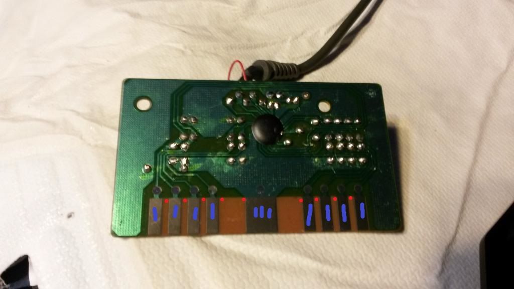
Alright, so I watched your video and could not tell very well where you were saying to drill on the board. I edited my picture in paint and put red dots where I THINK you were saying to drill, and then blue lines where it looked like you had laid the wires. I was also somewhat toying with the idea of getting a new DB15 female-female connector and doing the same thing you were doing and running new cables from the board to the connector, just to make it a bit cleaner.


Confirm on the blue lines just make sure to sand them down first. I actually did drill in those red spots between terminals such that it doesn't touch the adjacent terminal. This just makes it easier to solder the wires but if you just apply solder to the terminals and then to the wires that works even better. I believe that process is called tinning just lots of solder on the terminals and then a dab on each wire then solder them together and you get a really good connection.
Reply
So I finally got this control box set up and it appears to be working fairly properly, but I ran into one other issue:

I accidentally broke the breakaway cable that goes to the box on this, and have been unable to fully play because of it (The left arrow stopped being recognized by the cable unfortunately). All of my attempts to replace it so far have failed, with a regular VGA (M-M) cable not carrying the signal even with an adapter and a VGA (M-F) cable doing the same. I looked around and have been only able to find one possible replacement (found here: http://www.ddrgame.com/dance-dance-revolution-control-box-breakaway-cable-15-pin.html) and am still skeptical about whether it could work or not. Would it just be easier to "construct" my own VGA cable, or could I find one out there for a decent price?


On a second thought, would it be easier to change and rewire the connector on both the box and the pad to a female RJ45 breakouts or keystone connectors? I've seen people construct metal pads using them, and with CAT5e cables the wiring on them has to match up on both ends in order for the cable to even remotely work. That, and (to me at least) the connectors for them would be more sturdy than plugging in these DSUB-15 connectors.

Last edited: 6 September 2015 8:02am

Reply